~/notes/lasing-urp
Lasing URP
While working on a project to render a valley of realistic foliage in real time with Gaussian splats in Unity, I had the idea of putting on a laser show over it at night, cued to Ninajirachi’s “iPod Touch”.
This post is a collection of visualisations that follows the process of implementing semi-realistic laser rendering, from a first attempt that looked wrong to the renderer I ended up with; several of them are live WebGPU renders of a small version of it.
The timings are GPU times in Unity at 1920×1080 with the splats and foliage drawn, mostly from one fixed view 60 seconds into the show. In the final build, with the laser light switched off, the frame already takes about 13 ms of the 16 ms budget, mostly for the splats, which leaves the lasers about 3 ms.
Challenges in simulating lasers with shaders
This section starts from a first attempt that looks wrong and turns what is wrong with it into a list of challenges; the next section builds a renderer that takes on most of them.
A first attempt
In case you haven’t stood in front of one, a laser show fills the air with haze, a fine fog of water-glycol or glycerine droplets about a micron across. The beams are only visible where those droplets scatter light toward you1. The show I had in mind uses 12 laser projectors on moving heads around the valley.
My first attempt ignored the haze and drew each beam the way many games do, as a camera-facing ribbon with a soft glow.
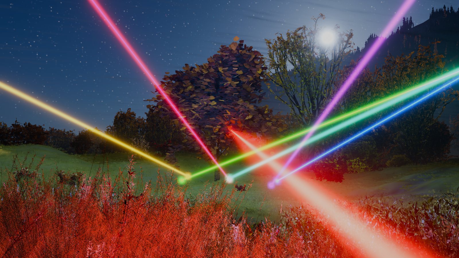
It doesn’t look like a laser show. The first things to notice:
- the beams are as wide a hundred metres out as they are at the projector;
- they are as bright seen from the side as looking down them;
- each fan of beams looks like a bundle of separate lights;
- where beams overlap, the colour washes out;
- the haze, the trees and the ground play no part.
Each of these leads to one or two of the challenges below.
Wider than a pixel, then thinner than one
The spec sheets I found give a show beam 4 to 7 mm across at the aperture, measured as the 1/e² diameter, which is , and a spread of 0.4 to 1.3 mrad2,3. At 1080p with the show camera’s 37° vertical view a pixel covers about 0.63 mrad, so seen from a metre or two away the beam spans several pixels, and from beyond about ten metres it is thinner than one. A sub-pixel line sampled at pixel centres flickers as it moves.
What a pixel should show is the beam convolved with the pixel’s footprint. Treating both as Gaussians, a beam of width seen from distance through pixels of angle has width on screen, with the footprint , so the beam gets wider and dimmer with distance and never thinner than about a pixel. The 0.6 is hand-tuned, a little softer than the 0.29 () a box pixel would give, because a line that is too sharp crawls. The renderer uses mm, about three times a real beam’s, which doesn’t matter beyond about a dozen metres because the footprint dominates there.
The beam and pixel curves cross about twelve metres out; beyond that the pixel, not the beam, sets the width you see.
Brightness depends on where you look from
The ribbons look the same from every side, and real beams don’t. The droplets in show haze are about the size of the light’s wavelength, and particles that size throw most of what they scatter forward. The exact angular pattern comes from Mie theory, that is, Maxwell’s equations solved for a sphere4, but it is a long series that depends on droplet size and wavelength, far too heavy to evaluate per pixel.
I hadn’t met the usual stand-in before this project. The Henyey–Greenstein phase function5 was proposed in 1941 to describe light scattered by interstellar dust, and its whole job is to capture how lopsided the scattering is with one number, the mean cosine .
One way to arrive at it is to ask for the simplest family where each higher-order term of the angular pattern shrinks by the same factor. Expand a phase function in Legendre polynomials; if the -th coefficient is , the series sums exactly to the expression above. So is isotropic, is a forward spike, and negative scatters backward. Blending a lobe like this with a second one fits Mie scattering by fog-sized droplets well6.
With the mix I ended up using, mostly a lobe at , looking 5° off a beam toward the projector is over a hundred times brighter than seeing it from the side.
One lobe is the my first renderer used, and two lobes is that mix. Raising sharpens the forward spike; the small backward rise is the second lobe, at , and the slider leaves it alone.
The beam moves faster than the frame
The fans in the first attempt looked like bundles of separate lights, and I couldn’t explain why real fans don’t. Reading up on how show projectors work answered it. A projector combines its lasers into a single beam steered by two small galvanometer mirrors, and a “fan” is that one beam dwelling on a few points in turn, while a “sheet” is the beam swept back and forth7. The projector’s scanner runs at 20,000 to 60,000 points a second8, so a 60 fps frame holds 330 to 1,000 points, and the eye adds them up into a fan.
Sampling the scanner once per frame sees one beam in one place, the dots on the trace, while frame 2 exposed every angle in its histogram. The figure starts at 3,000 points a second, well below a real scanner, so single points stay visible, and its moves between points are illustrative.
Switch to the sheet and the histogram piles up at the ends. A mirror driven sinusoidally, with the normalised position across the sweep and the sweep frequency, is fastest at the centre and stops to turn round at the ends9. The time it spends near is , which normalises to the arcsine density .
The power is shared
The same reading explained the washed-out colour. Since a fan is one beam visiting points, each point gets about of the projector’s power, less what the moves between points waste10. Drawn as 40 beams that each carry a whole projector’s power, a 40-point fan is 40 projectors’ worth of light, and 12 projectors of that wash the sky to white.
Colours outside the screen
Monochromatic light sits on the curved edge of the CIE 1931 chromaticity diagram, so laser lines are far outside the sRGB triangle11. A 520 nm green clips to the screen’s pure green, and a per-channel curve such as Reinhard’s holds it there however bright it gets, so it never whitens. The trouble is the other lines and the rest of the chain. A 445 nm blue clips with some red in it and drifts to magenta as it brightens, overlapping beams mix channels, and the frame’s final tone map works against lasers on purpose.
I looked into why. The frame uses AgX12, a tone map that, like film, desaturates colours as they approach the top of its range, so that a sunlit sky fades to white rather than turning flat cyan. A saturated laser line is exactly what it is built to bleach.
So I ease the laser light before it joins the frame, which keeps it lower in AgX’s range, where it bleaches less. Its peak channel goes through , with chosen by eye so a single beam’s core stays saturated while dense fans still compress. The other channels scale with it so the hue holds, and 8% of what the curve removes is added back, mostly as white.
The per-channel ramp of the 445 nm line drifts in hue as it brightens, while the eased ramp keeps its hue and gains a white core.
The scene gets in the way
Beams pass through canopies, stop at the ground and light what they land on, and the haze dims them along their length. All of that has to happen per pixel, for 12 projectors with up to 40 beams each, in about 3 ms.
The first compute and shading implementation
This section builds my first real renderer, which I’ll call the per-beam renderer, then measures it.
Single scattering along a view ray
If the light is in the air, I should shade the air. For a pixel looking along from , the light the haze scatters toward the eye along , up to the first surface at , is13
Here is the haze scattering coefficient, the phase function at the angle between the beam and the ray, the irradiance from a projector at distance whose intensity in the direction toward is , what the leaves and haze have left of the beam, and the transmittance on the way back, with the background haze. The extinction factor of 0.6, unrelated to the footprint’s, is there because haze droplets scatter mostly forward, so light heading to the eye loses less than the full haze value would remove. uses only the background haze, because the plumes and smoke are local, and including them would mean a second march along every view ray for a small change in brightness. I shade only light scattered once, and use a blurred glow to approximate the light scattered twice.
The background haze is 0.02 m⁻¹. The field thins with height above the valley floor and is broken up by slowly drifting noise, four haze machines add plumes that widen downwind, and the fireworks in the show add puffs of smoke that spread and fade.
The first pass, built up
Each frame the CPU hands the GPU a list of beams, and a chain of compute passes and a composite turn it into the light in the haze and on the ground.
Beams (CPU)
Let the show have projectors. Projector sits at and aims along yaw and pitch . Each angle is driven toward its target, away, by a critically damped spring, with time in seconds,
and likewise for .
class Head// one projector{ Vector3 at;// where it hangs float yaw, pitch;// where it points, on its spring float yawSpeed, pitchSpeed;}const float k = 90f, c = 19f;// c = 2 sqrt(k)h.yawSpeed += (k * dy - c * h.yawSpeed) * dt;h.yaw += h.yawSpeed * dt;
Each frame, projector draws its pattern as beams , each with the projector’s full power .
for (int k = 0; k < n; k++){ var d = BeamDir(h, h.yaw, h.pitch, h.spin, k, n); Put(h.at, d, colour * h.power, 0);}
A beam is the record , holding its start , width , end , the length its shadow table covers, its power in each colour channel , and a kind , which is 0 for a plain beam.
struct Beam// 48 bytes, up to 2048 a frame{ float4 a;// start; w = sigma, 4 mm float4 b;// end, 400 m out; w = table length float4 colour;// rgb = P colour; w = kind};
If a beam turned through an angle since the last frame, with , it is emitted as a sweep of two records, since below 0.15° the move is within the beam’s own width; take to mark them as the edges bounding the wedge it swept.
float swept = Vector3.Angle(was, d);if (swept > 0.15f && swept < 60f){ Put(h.at, was, colour * p, 1);// the edge it left Put(h.at, d, Color.black, -1);// the edge it reached}
Clip
March from along the beam, with the distance from , in steps of m, for at most 600 steps.
for (uint i = 0; i < 600 && t < reach; i++){ t = min(t + max(0.25, t * 0.012), reach); float3 p = a + d * t;
At the first step below the ground, bisect 10 times. The hit defines the beam’s length .
if (p.y > HeightAt(p.xz)) { last = t; continue; } for (uint k = 0; k < 10; k++)// bisect { float m = (last + t) * 0.5; if (HeightAt(a + d * m) < (a + d * m).y) last = m; else t = m; } break;}float len = t;
Along the beam, with the extinction coefficient of the foliage, integrate the optical depth of leaves and haze
while (s < to){ float step = min(clamp(s * 0.03, 0.4, 4), to - s); depth += (FoliageAt(m) + Haze(m)) * step; s += step;}
Store the transmittance at , ; the quadratic spacing puts more entries near the projector, where errors show most.
for (uint j = 1; j < 32; j++){ float to = len * (j / 31.0) * (j / 31.0); // ... march to 'to' ... table[j] = exp(-depth);}
Tiles
Divide the screen into tiles of px.
[numthreads(64, 1, 1)]// one group per 16 x 16 tilevoid Tiles(uint3 g : SV_GroupID, uint index : SV_GroupIndex){ uint tile = g.x; float2 lo = TileMin(tile), hi = lo + 16;
Beam projects to a capsule of radius
where is the camera depth of its nearer end.
float2 pa = ToPixel(a, wa), pb = ToPixel(b, wb);float radius = max(4 * sigma / (max(min(wa, wb), 0.2) * _PixelAngle), 3) + 2;if (!SegmentMeetsRect(pa, pb, lo - radius, hi + radius)) continue;
Tile keeps the list of beams whose capsule meets it.
uint k;InterlockedAdd(gCount, 1, k);_TileBeams[tile * PER_TILE + k] = i;
Each list holds at most 384 beams, a fixed size that no tile came near at any moment I measured, the song’s densest look included. Further beams would be dropped, and which ones depends on thread timing, so it could change from frame to frame.
if (k < PER_TILE) ...// PER_TILE = 384 _TileCount[tile] = min(gCount, PER_TILE);}
Scatter
The pixel’s view ray is , .
float3 o = _Eye, u = normalize(hit - o);float reach = length(hit - o);
Its radiance is the sum over its tile’s beams, .
float3 sum = 0;for (uint k = 0; k < _TileCount[tile]; k++){ Beam beam = _Beams[_TileBeams[tile * PER_TILE + k]];
For beam with axis , let and be the parameters of the closest points of the two lines, their distance, and .
float c = dot(u, v), e = dot(u, r), f = dot(v, r);float den = max(1 - c * c, 1e-6);float w = clamp((f - c * e) / den, 0, len);float s = max(dot(a + v * w - o, u), 0);float d2 = dot(o + u * s - (a + v * w), o + u * s - (a + v * w));
Let , with the pixel footprint . Beams with are skipped.
float sigma2 = sigma * sigma + pow(s * _PixelAngle * 0.6, 2);if (d2 > 25 * sigma2) continue;float across = min(1 / (2.5066 * sqrt(sigma2) * max(sqrt(den), 1e-3)), len / (6.2832 * sigma2));
With the phase function and the haze at the closest point,
As the factor is capped at , its value for a ray running down the axis for the beam’s whole length .
sum += beam.colour.rgb * Haze(pb) * Phase(dot(v, -u)) * exp(-d2 / (2 * sigma2)) * across * BeamLeft(index, w, len) * exp(-_Haze * 0.6 * s);}
Surfaces
If the ray ends on a surface at distance from the axis, the irradiance there is
and a diffuse surface of albedo returns .
float ws = clamp(dot(hit - a, v), 0, len);float3 off = hit - (a + v * ws);sum += beam.colour.rgb * _SurfaceGain * exp(-dot(off, off) / (2 * sigma2s)) / (6.2832 * sigma2s);
Here , with the footprint at the surface, so the spot is never narrower than about a pixel.
float footprint = reach * _PixelAngle * 0.6;float sigma2s = sigma * sigma + footprint * footprint;
Persist
Let be a pixel’s scattered light this frame and the time since the previous frame.
_Now[id] = sum;// this frame's scattered lightThe trail is , per pixel, with the previous frame’s trail and a decay time.
_Trail[id] = max(_Now[id], _Trail[id] * _Decay);Take ms, within the 50 to 100 ms over which the eye adds up a flash14, which I come back to under persistence.
_Decay = exp(-dt / 0.07);// C#: 70 ms to 1/eGlow and composite
The glow is the trail blurred at six widths and summed. It approximates light scattered twice, which leaves the beam in every direction and arrives from a wide halo around it; a sum of blurs of the once-scattered light imitates that at a fraction of the cost.
for (int g = 0; g < 6; g++) GlowDown(g);// 13 tapsfor (int g = 5; g > 0; g--) GlowUp(g);// 3 x 3 tentfloat3 twice = _GlowTex.SampleLevel(s, uv, 0).rgb / 6;
When a projector points near the eye, add a veil of its colour, which grows as the beam’s angle to the eye shrinks and stands in for glare in the eye and the lens.
h.glare = h.power * exp(-off * off / 1.5f);// off: degrees from the eyeveil += colour * h.glare * 0.04f;
The colour has peak channel . The peak is eased to and the colour scaled with it, which keeps the hue, and 8% of the excess is added back, mostly as white ,
float3 c = (once + twice * 0.06 + _Veil) * _NightEyeScale;float peak = max(max(c.r, c.g), max(c.b, 1e-5));float eased = peak * 3 / (3 + peak);float3 kept = c * (eased / peak);// the hue keptfloat over = max(peak - eased, 0);return kept + over * 0.08 * (kept / max(eased, 1e-5) * 0.4 + 0.6);// 8% back, mostly white
The first pass in a real frame
The walkthrough is drawn, not measured, so I wanted to see the passes themselves. I read their buffers back from the GPU for one frame, 60 seconds into the show; the tile counts come from the per-beam renderer, and the glow and composite passes are the same in both.
The busiest tiles run along the horizon, where the beams converge on their projectors. No tile weighs more than 32 of the frame’s 328 beams, an eighth weigh none, and none comes near the cap of 384.
The first time I read the lists back they looked nothing like this. Every tile, the grass at the bottom of the frame included, listed between 127 and 159 beams. A sweep with a corner close to or behind the eye can’t be projected to the screen as it stands, and the tile test handled that case by listing it in every tile. The drop’s fans are aimed over the audience, so the far ends of their sweeps lie behind the camera, and nearly every sweep in the frame took that path. Clipping each sweep at the camera’s near plane before testing it gives the lists above. What the bug had cost I only measured once the maps were built, and I come back to it there.
Across one row of the frame the trail is a comb of sharp beams. Each blur level smooths it further, and what the composite adds, 0.01 G, is a smooth floor about thirty times under the brighter beams that rises where they gather. It reads as a halo round them, not as wider beams.
About 3.5% of the pixels reach the knee, so it shapes the beams’ cores and the brightest crossings and leaves the rest of the frame alone. In a quiet part of the song fewer than 0.5% reach it, and just after a firework about 1.3%.
The beam integral in detail
The Scatter formula is exact for a straight Gaussian beam, as long as , and don’t change across its few millimetres. Along the ray the squared distance to the axis is , and a Gaussian integrates to times its width.
The ray passes the axis at distance and angle ; the end view shows the beam’s and the wider a pixel sees.
P · e−ϱ²/2σ² / (2π σ²)
a Gaussian tube of width σ
The closed form breaks down end on, where the ray runs inside the beam for its whole length and and change along it. It stays within 1% down to about 0.05°. Below about 0.004° the cap takes over and overestimates by about 4×, because it uses one for widths from millimetres to centimetres. That is a tiny cone around each axis, and those pixels are saturated anyway.
In the shader, Scatter’s inner loop finds the closest points of two lines, culls beams that are too far away, and evaluates the closed form with two exponentials and no loop along the ray.
// closest points of the view ray o + u s and the beam a + v zfloat3 r = o - a;float c = dot(u, v), e = dot(u, r), f = dot(v, r);float den = max(1 - c * c, 1e-6);float z = clamp((f - c * e) / den, 0, len);float s = max(dot(a + v * z - o, u), 0);float3 pr = o + u * s, pb = a + v * z;float d2 = dot(pr - pb, pr - pb);float fp = s * _PixelAngle * 0.6, sigma2 = beam.a.w * beam.a.w + fp * fp;if (d2 > 25 * sigma2) continue;float sine = sqrt(den), sigma = sqrt(sigma2);float across = min(1 / (2.5066283 * sigma * max(sine, 1e-3)), len / (6.2831853 * sigma2));// capped end onfloat transmit = exp(-_Haze * 0.6 * s);sum += HazeTint * beam.colour.rgb * Haze(pb) * Phase(dot(v, -u)) * exp(-d2 / (2 * sigma2)) * across * transmit * shown * BeamLeft(index, z, beam.b.w) * Sparkle(pb, s);
Line 9 is the footprint added in quadrature, and line 13 is the end-on cap.
From the side the beams are faint threads, and raising dims them further, because the forward lobe takes light from the side. Look down one and it flares.
Analysis
It looked close in stills, so I measured what each part cost by switching it off. This was the first build, before I lowered the splat detail.
Most of the frame was the splats, and drawing them at slightly lower detail brought the whole frame to 19.2 ms. My first suspect was the haze, since every beam evaluates it at every pixel it touches, so I baked it into a 3D texture once a frame.
I reasoned that the loop’s cost is roughly the sum, over all pixels, of the number of beams listed in each pixel’s tile. A fan of 40 beams puts 40 entries in every tile near its projector, a moving projector doubles them with sweep pairs, and fans from different projectors cross over the middle of the screen.
The figure has three projectors rather than 12, and even so the busiest tiles are the ones where fans cross.
Problems
Measuring it, and setting it against what I had read about real projectors, showed me five problems. Problems 1, 3 and 4 share a cause, and 2 and 5 are modelling errors.
- The cost grows with the beam count. A fan of points is entries in every tile it crosses, and every pixel in that tile pays for each. Dense fans are the point of a laser show, so with the scatter pass at 6.6 ms this looked like the wrong thing to scale with. Most of that 6.6 ms was the tile bug, so the problem was far smaller than it looked; how small comes after the maps.
- Every beam has a whole projector’s power. A 12-beam fan was 12 projectors’ worth of light, so dense moments washed to white.
- Time is sampled only twice per frame. A sweep is the wedge between the last pose and this one, so the hundreds of points the scanner visits in between, which make a fan’s dwell points and a sheet’s bright edges, never appear.
- Persistence lives in screen pixels. The trail is kept per pixel, so when the camera turns, it stays where the beam was on the screen, not where it was in the world.
- The haze looks too similar from every side. A single lobe at has neither the forward peak nor the small backward rise of real droplets6.
Revisions
The two modelling errors needed only small changes. The other three looked unrelated, but each traced back to where I added up the light, which was on the screen, per pixel and per beam. The cost grew with the beams because every pixel summed every beam in its tile, time was sampled twice a frame because a pixel could only afford two poses of each beam, and the trail stayed on the screen because that was where the sum was kept. A projector’s light doesn’t depend on where the camera is, so it can be added up once, before any pixel asks for it. That pointed to moving the work, that is, adding up each projector’s light in its own space first and letting each pixel look it up.
One scanned beam per projector
The first thing the reading made obvious, though I added it last, was that I had been drawing projectors that don’t exist. A real projector is one beam with one power budget, scanned, so I modelled it that way.
- Shared power. Each projector now has one power budget, shared across its pattern. The per-beam renderer gave every beam the same fixed power, and the budget is six times that, a value I set by eye, so a single beam is six times brighter than before and each beam of a 40-point fan gets a fortieth of the budget.
- Sheets. A sheet is one line swept back and forth. When the projector is stepped through the frame, as described in the next section, each step lays the line down in four pieces, and each piece gets its share of the arcsine density, for the piece from to across the sheet; within a piece the ends are brightened smoothly, as the walkthrough below shows.
With the power budget, dense fans no longer add up to white, so the colours hold and the trees and sky show between the beams. Both renders below already use the exposure maps of the next section.
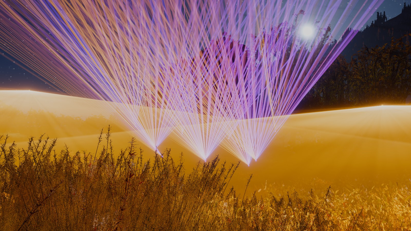
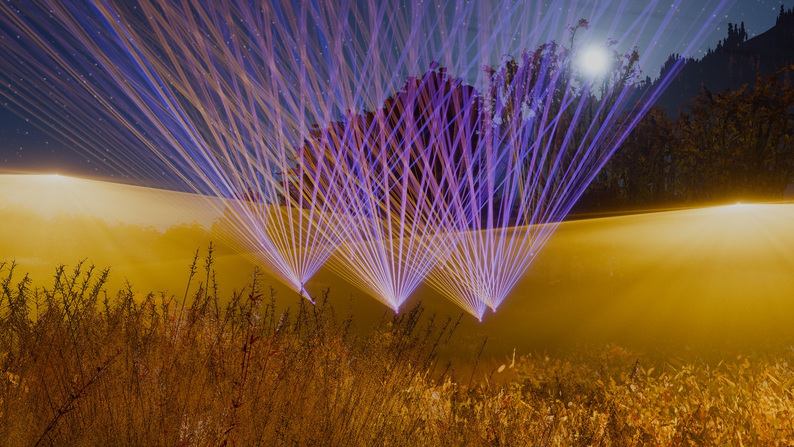 before after
The bright edges of the sheet below are not drawn by the shader. It is rendered from its simulated scan alone, and its profile, read back from the exposure map I describe next, follows the arcsine curve because the mirror spends more time at the ends.
Accumulating in exposure maps
Once a projector is a scanned beam, the natural question is where else the adding-up could happen. My first instinct was a 3D grid in the world, accumulating energy wherever the beams passed, but the numbers rule it out. A beam is millimetres wide and hundreds of metres long, so a grid fine enough to hold it would be enormous, and almost all of it would be empty.
A projector’s light, though, only ever leaves along straight rays from one point. Seen from the projector, a beam is not a long thin volume but a single direction, so I accumulate in each projector’s own space of directions, before any camera looks at it. Each projector is stepped many times through the frame, and every step lays down where its beams pointed into a 2D map of directions. At the end of the frame the map holds the projector’s exposure
with the beam’s direction and its power at time . That is the scan-trace histogram in two dimensions, per projector. Apart from the map’s resolution, nothing is lost by storing it this way, because the irradiance at any point comes back as the map’s intensity over , with a per-projector shadow table supplying what the leaves took on the way. Building it costs work per beam and time step, in the map’s few hundred thousand texels rather than the screen’s two million pixels, and shading marches through it once per projector per pixel however many beams the pattern has, though a denser pattern leaves fewer empty cells for the march to skip. Shadow maps15 and photon maps16 make the same trade, doing the work in the light’s space and looking it up from the camera.
That left the question of how to lay out a map of directions. Each pixel will have to walk its view ray through every projector’s map, so I wanted a layout in which a ray is easy to walk. The gnomonic projection, that is, the one a pinhole camera uses17, stores each direction where it pierces a flat plane one unit in front of the projector. It has the property I needed. A straight line in space and the projector together span a plane, and that plane meets the map plane in a line, so every view ray’s image in the map is a straight segment.
Per frame, the algorithm steps each projector through the frame, lays its paths into its map, resolves the map and its shadow table, and marches each pixel’s view ray through every map.
Expose (CPU)
Projector has a map with orthonormal axes , with the mean direction of its beams. Direction maps to the tangent coordinates
and to texel , with the map’s corner and the pattern’s extent over 504 texels; the map is 512 texels across, with 4 texels of padding on each side.
var z = mean(pathEnds).normalized;// the mean beam directionvar x = Vector3.Cross(Vector3.up, z).normalized;var y = Vector3.Cross(z, x);Vector2 Tan(Vector3 d) => new Vector2(Vector3.Dot(d, x), Vector3.Dot(d, y)) / Vector3.Dot(d, z);float tau = extent / (512 - 2 * 4);// a texel, in tangent units
Let be the largest angle the first, middle and last beams moved since the last frame.
float swept = 0;foreach (int k in new[] { 0, n / 2, n - 1 }) swept = Mathf.Max(swept, Vector3.Angle(lastDir(k), dir(k)));
Divide the frame into time steps, at least one. At 0.1° a step’s chord stays close to the true arc, and 64 caps the CPU cost per projector per frame.
int steps = Mathf.Clamp(Mathf.CeilToInt(swept / 0.1f), 1, 64);If , take ; a move that large in one frame is a cut between looks, not a sweep the eye would see.
bool jump = swept >= 60f;if (jump) steps = 1;// only where it is now
In each step, each beam’s path from its previous direction to its new one becomes a chord from to in the map, carrying energy .
for (int j = 1; j <= steps; j++){ var d = BeamDir(h, YawAt(j / (float)steps), PitchAt(j / (float)steps), ...); var a = (Tan(prev) - origin) / tau, b = (Tan(d) - origin) / tau; segs.Add(new Seg(a, b, colour * P / (n * steps), head)); prev = d;}
Cells
A cell is a block of texels. Mark every cell a chord passes through.
int marks = Mathf.CeilToInt((b - a).magnitude / 2) + 1;for (int m = 0; m <= marks; m++){ var c = Vector2.Lerp(a, b, m / (float)marks) / 8;// 8 x 8 texels a cell touched[(int)c.y] |= 1ul << (int)c.x;}
Mark each marked cell’s eight neighbours too. The march tests only the cell at the middle of each 8-texel span, and a span can straddle two cells.
for (int r = 0; r < 64; r++) for (int dr = -1; dr <= 1; dr++) row[r] |= touched[r + dr] | touched[r + dr] << 1 | touched[r + dr] >> 1;
Store the marks as one bit per cell.
cells[(head * 64 + r) * 2] = (uint)row[r];cells[(head * 64 + r) * 2 + 1] = (uint)(row[r] >> 32);
Deposit
Sample the chord at points, two a texel. Each point is weighted by the angle it covers since the previous point.
struct Seg { float4 ends; float4 colour; float4 info; };// 48 bytes uint n = min((uint)ceil(len * 2), 4096u);// 2 points a texelfor (uint k = 0; k < n; k++){ float w = acos(saturate(dot(prev, d)));// the angle it covers
On a sheet, with the point’s position across it, .
if (g.info.y > 0.5)// a scanned sheet w *= 1 / sqrt(max(1 - x * x, 0.04));
Normalise the weights to sum to 1 over the chord, so it deposits exactly its energy . Split each point bilinearly over its four texels, with weight on each.
Splat(h, lerp(a, b, f), g.colour.rgb * (w / total));}void Splat(uint h, float2 m, float3 e)// bilinear, 4 texels
GPUs add integers atomically but not floats portably, so add to the texel’s integer counter . The factor 4096 keeps small deposits from rounding away without overflowing at show brightness.
{ uint3 q = (uint3)(e * weight * 4096 + 0.5); InterlockedAdd(_MapAccum[at], q.r);}
Resolve
Write to a half-float texture, and clear for the next frame.
float3 e = float3(_MapAccum[at], _MapAccum[at + 1], _MapAccum[at + 2]) / 4096;_MapAccum[at] = 0; _MapAccum[at + 1] = 0; _MapAccum[at + 2] = 0;_MapOut[id] = float4(e, 0);
Build its mips; level holds the exposure as seen through a beam texels wide.
cmd.GenerateMips(maps);Shadow table
Take a grid of directions across the map.
float2 m = (id.xy + 0.5) / 32 * mapSize;// 32 x 32 directionsfloat3 d = MapDir(h, m);
For each, store the light left at m, .
float len = MarchLeft(head, d, 400, table, landed);for (uint k = 0; k < 32; k++)// onto 400 (k/31)^2 _MapTOut[uint3(id.xy, h * 33 + k)] = TableAt(table, len, 400 * f * f);
Also store , the distance at which the direction meets the ground.
_MapTOut[uint3(id.xy, h * 33 + 32)] = landed;March
Let and be the eye and the view direction relative to the projector, in the map’s axes, so the ray is with tangent . Clip to the map’s frustum, up to 600 m. Each of the four edge bounds on and is linear in once multiplied by , and keeps the ray in front of the projector.
float lo = 0, hi = min(reach, 600);for (uint i = 0; i < 4; i++)// each map edge: linear in s{ float sb = -c0[i] / c1[i]; if (c1[i] > 0) lo = max(lo, sb); else hi = min(hi, sb);}
With the clipped range, the ray’s image is the straight segment from to .
float2 m0 = (float2(ax + bx * lo, ay + by * lo) / (az + bz * lo) - origin) / tau;float2 m1 = (float2(ax + bx * hi, ay + by * hi) / (az + bz * hi) - origin) / tau;
Walk the segment in spans of 8 texels, skipping spans whose middle lies in an unmarked cell.
for (uint c = 0; c < spans; c++)// 8 texels a span{ if (!CellTouched(h, m0 + along * (c + 0.5) * 8)) continue;
Take samples per span. For a sample at distance from the projector, with beam width , divergence and footprint , the beam’s width in texels is
float wide = max(max(waist / r, divergence), footprint / r) / tau;uint steps = clamp(ceil(8 / max(wide, 1)), 2, 8);
A sample at tangent along the segment (or , whichever changes faster) lies at
float s = (ax - t * az) / (t * bz - bx);// where the ray crosses map column tThe sample reads mip level , where accounts for texels covering less angle away from the map’s centre, and adds, with the spacing of the samples,
float lod = log2(max(waist / r, divergence, footprint / r) * q / tau); float3 I = _Map.SampleLevel(sampler, float3(m / 512, h), lod).rgb * q * sqrt(q) / (tau * tau); sum += I * Haze(x) * Phase(dot(dir, -u)) * MapLeft(h, m, r) * ds / (r * r);}
Surfaces and the sum
A surface point reads one texel per projector, the one its direction from the projector maps to.
float3 q = hit - head;float2 m = (float2(dot(q, X), dot(q, Y)) / dot(q, Z) - origin) / tau;return MapSample(h, m, length(q), footprint) / dot(q, q) * MapLeft(h, m, length(q) - 0.5);
The pixel’s radiance is , so each pixel does one march and one lookup per projector, however many beams there are; what the beams change is how much of each march can be skipped.
for (uint h = 0; h < _MapCount; h++) sum += MapMarch(h, o, u, reach) + MapSurface(h, hit, footprint);
The in the last beat comes from solid angle. At tangent position a texel of size covers a solid angle , so its intensity is its energy over that. The single-scattering integral becomes a sum over the samples along the ray’s image, apart
The figure’s map is 64 texels across, with a wider beam so the change in steps per span is visible; the real one is 512.
A few cases need care.
- Rays along a projector direction, such as one looking down a beam, have an image only a few texels long, so a few samples carry the whole ray. It is the same end-on case as the closed form, and here it is limited by the mip, which can’t be finer than one texel.
- Behind the projector’s plane the ray is clipped away, and directions more than 75° from the map’s centre are dropped when depositing, because a texel there covers almost 60 times less solid angle than one at the centre.
- Map resolution is the pattern’s extent over 504 texels, on average about 2.4 mrad for a 70° sheet, nearly four pixels at 1080p, so close parallel beams blur into each other.
- Shadows come from the 32×32 table, so beam ends on the grass are soft.
What the maps cost
My first build of the maps was 3.0 ms slower than the per-beam renderer it replaced. I had built them expecting them to be faster, so I set out to find where the time went. Two tests split the cost.
| change | GPU ms | conclusion |
|---|---|---|
| maps, as built | 22.18 | |
| march returns 0 | 13.78 | the march costs about 8.4 ms |
| constant haze in the march | 17.82 | haze lookups cost about 4.4 ms of it |
The march evaluates the haze at every texel it crosses, where the closed form evaluated it once per beam. So here the haze was the cost, and the haze texture that did nothing for the per-beam renderer went back in and saved 3.6 ms. Then I made the skip cells smaller, 8 texels instead of 16, and let the march take fewer steps where the beam is wide. That reached 17.3 ms against 18.5 ms for the per-beam renderer measured again in the same build, and at the time I took the difference as the maps’ gain.
That comparison was against the tile bug rather than the per-beam renderer. Once the lists were fixed I measured both paths again, interleaving their runs at five moments of the song, and the per-beam renderer was the cheaper at every one. 60 seconds in, its frame takes 13.8 ms against 16.2 ms for the maps, and its laser passes about 0.9 ms against 3.3 ms. The gap is 0.9 ms at the quietest moment I measured and 3.7 ms just after a firework, where the maps’ frame reaches 18.2 ms. Most of the maps’ cost is the per-pixel pass that holds the march, which takes 0.8 to 4.3 ms over those moments; depositing, resolving and the shadow tables take 0.6 to 0.8 ms together, and stepping the projectors up to 1.85 ms of CPU.
The bug also explains the first measurements. With every tile listing 127 to 159 beams, the loop visited about a million entries a frame, some thirty times what the fixed lists hold, which would account for most of the 6.6 ms the scatter pass cost in the first build.
To see how each path scales, I forced every projector’s pattern to the same number of beams, from 1 to 80, at a moment when all 12 projectors are sweeping.
The per-beam renderer grows with the beam count, as problem 1 said, but slowly; its tile and loop passes go from 0.12 ms to 1.2 ms over the whole range, and the frame stays within the noise of 13.5 ms. The maps grow faster, from 13.7 ms to 18.7 ms, because a denser sweeping pattern marks more of each map’s cells and leaves the march less to skip. The two never cross, and the gap widens with the beam count. I also tried finding each pixel’s beams with signed distance fields instead of screen tiles; the appendix has the result.
So the exposure maps are not a speed-up. They cost more than the renderer they replaced, and their cost follows how much of the screen and of each map the patterns cover. What they buy is the light itself.
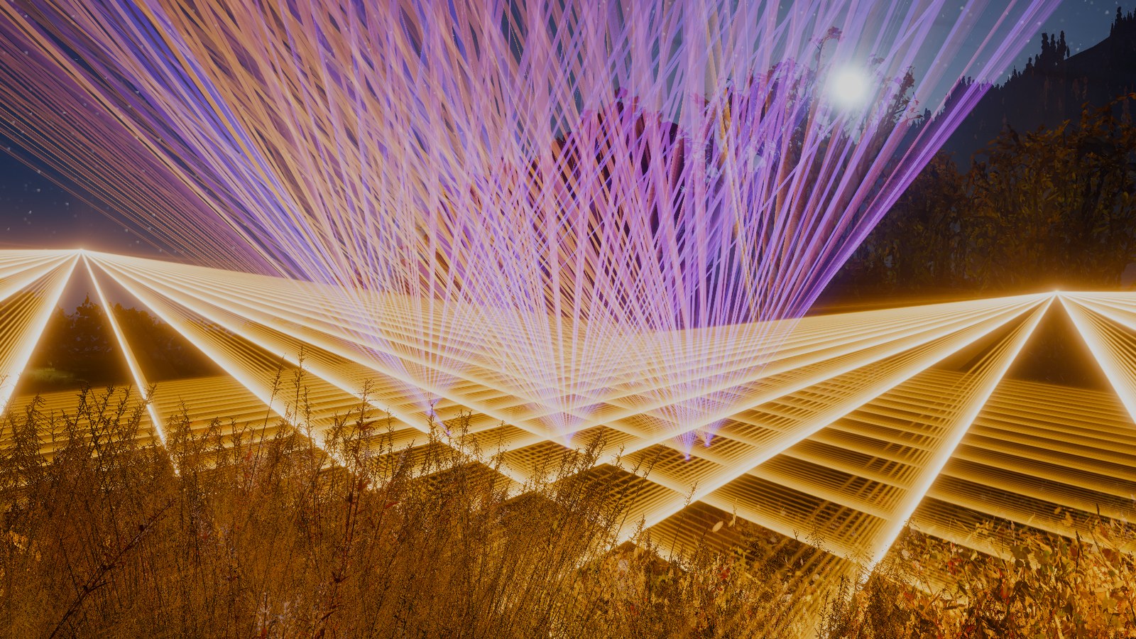 per beam exposure maps
Per beam, the sheets over the grass are bundles of separate lines; from the maps, the light between them fills in and each reads as one sheet.
The maps in a real frame
The same frame’s exposure maps show each projector’s light before any camera looks at it.
Each fan beam is a short streak, the projector’s swing during the frame; the cone’s beams are dots along a curve, and the sheet is one band. The pale cells are the ones the march can’t skip, 8% of the cone’s map, about 70% of the fan’s and all of the sheet’s.
Across its line the sheet’s light rises at both ends; each of its four pieces was given its share of the arcsine density, and the map keeps it, with small steps where the pieces meet.
Persistence in screen space and in world space
The maps also changed how I thought about persistence, the reason a scanned fan looks solid at all. I wanted to know how long the eye’s window is, and found Bloch’s law14; for flashes shorter than roughly 50 to 100 ms, perceived brightness depends only on intensity times duration, as if the retina integrated the light over that window, so several brief passes inside it look like one longer pass with the same energy. My first renderer kept that sum in screen pixels because that was where the light was. The question I should have asked is what happens when anything moves.
Following one pixel over 200 ms shows the difference.
The pulses on top are the true signal, each a pass of the scanner over this pixel’s direction, and the lane under it is one sample a frame. With the camera panning, the pixel sees the beam only briefly, and both screen-space lanes, the trail and a blend of each frame with the last as temporal anti-aliasing does, keep glowing where the beam no longer is; the exposure map doesn’t. The bottom lane is the true signal as the eye would sum it.
In the show, 60 seconds in, a tenth of the trail’s light comes from earlier frames; in a quiet part of the song almost none does, and as waves roll across the crowd, or just after a firework, over half does.
In the live render the difference shows when the camera moves. The screen trail smears, and at low scan rates flickers, while the exposure map stays solid, because it doesn’t know where the camera is.
Side by side, the two ways of adding up the light differ like this.
| screen space (per-beam renderer) | world space (exposure maps) | |
|---|---|---|
| scan samples per frame | 2 (last pose, this pose) | up to 64 |
| work to add up the light | per pixel × per beam | per time step, then per pixel × per projector |
| fan of points | entries in each tile it crosses | one map, with fewer empty cells to skip |
| camera moves | trail smears on screen | nothing to smear within a frame |
| limit | two poses a frame | map resolution |
The Unity show still keeps the 70 ms screen trail on top of the maps. Within a frame the maps already integrate the scan, and the trail only covers persistence across frames, where at 70 ms its smear is short. There are two ways to remove it.
- Reproject the trail with motion vectors. This works poorly for haze, because a pixel’s laser light comes from points all along its ray, not from one depth, so there is no single motion vector to follow.
- Keep each projector’s map from frame to frame with the same decay, in the projector’s own space. That is the right one, since the decay would happen per projector direction and never smear when the camera moves.
Checking the maps against the eye
So far I have judged the approaches by looking at them, and the timeline’s bottom lane sums the light with a single exponential I picked, not a model of the eye. This section builds a model of the eye’s own adding-up to serve as the reference, looks again at how the live figures lay down their maps, and then sets the trail and both kinds of map against the eye at one moment.
A model of the eye
The trail and the maps all try to reproduce what a viewer perceives, so the honest reference is the eye’s integration itself, not a denser version of one of them. Bloch’s law gives the length of the eye’s window but not its shape, so I read up on how vision researchers model it. Watson’s chapter on temporal sensitivity18 treats the eye’s response to a brief flash as light passing through a chain of identical first-order low-pass stages, each relaxing with the same time constant. The idea goes back to Fuortes and Hodgkin19, who fitted such a chain to the photoreceptors of the horseshoe crab and found that it runs faster as the light gets brighter. Passing a flash through the chain convolves one decaying exponential per stage, which gives a smooth bump of unit area. Watson’s model has two such chains, and I use the first, with nine stages.
His full model subtracts the second, slower chain from the first, which makes it respond to flicker more than to steady light. I left that term out, because it describes whether flicker can be detected at all. A light flickering too fast to see looks as bright as a steady light of the same mean, the Talbot–Plateau law that Watson also discusses18, and only a filter of unit area keeps that property; the full filter dims steady light and can even go negative.
I treat each pixel as a fixed point on the retina, which is right for an eye that fixates a point on the screen. An eye that follows the moving scene holds the tracked part still on the retina instead, so that part is not smeared; smooth pursuit manages this with a gain of about 0.9 up to roughly 100° a second20, and I didn’t model it. The beam itself sweeps at thousands of radians a second, far beyond any pursuit, so the scan’s persistence always comes from the eye’s integration.
Per frame, each pixel cuts the frame into short blocks, works out the light reaching it in each block exactly, and advances its stages by the exact solution for that light.
Stages
Let be the light reaching a pixel. The eye’s response is a chain of stages , each relaxing toward the one before with time constant ,
and is what the eye sees. Each pixel keeps its nine stages from frame to frame.
#define STAGES 9RWStructuredBuffer<float3> _EyeState;// STAGES planes of the frame's pixels, stage k at k * pixelsfloat3 y[STAGES];// the pixel's stages, kept from frame to frame[unroll] for (uint k = 0; k < STAGES; k++) y[k] = _EyeState[k * pixels + pixel];
A unit flash at leaves equal to the impulse response
which peaks at .
// h(t) = t^(n-1) e^(-t/tau) / (tau^n (n-1)!), n = 9, unit area, // so a fused flicker looks as bright as its mean
Time constant
The window shortens as the eye adapts to brighter light. Watson summarises its length, the critical duration , as falling from about 100 ms in dim light to about 25 ms in bright light, over four decades of retinal illuminance18, and I interpolate log-linearly between. I set the adaptation one decade above the dim end of that range, a night-time level of my own choosing rather than a measured one, which gives ms.
// critical duration ~100 ms at 1 td falling to ~25 ms at 10^4 td (Watson 1986), log-linear // between, at an adapting 10 tdpublic static readonly float EyeTc = 0.1f * Mathf.Pow(0.25f, Mathf.Log10(10f) / 4),
For this chain , the ratio Watson’s chapter gives for the same nine stages, 57 ms at ms18. So ms, and the window is close to the trail’s 70 ms.
EyeTau = EyeTc / 9.12f;// Watson's 9-stage filter has a critical duration of 9.12 taucmd.SetComputeFloatParam(cs, "_EyeTau", EyeTau);
Blocks
Cut each frame of length into blocks of length , about a quarter of a millisecond at 60 fps.
#define BLOCKS 64float D = _ScanDt / BLOCKS;[loop] for (uint b = 0; b < BLOCKS; b++){
Over block , replace the light reaching the pixel by its exact mean , with each head held at its pose at the block’s middle. Light that changes within the block then reaches the stages less than early or late, which is small against , about 30 times longer.
float3 x = 0;// the light at the pixel, its mean over the block for (uint h = 0; h < _MapCount; h++) if (MapSpan(h, o, u, reach + 1, lo, hi))// the ray passes through the head's map x += HeadLight(h, o, u, reach, surface, o + u * reach, footprint, b * D, D); // the head at its pose in the block's middlePose p = PoseAt(h, l0 + 0.5 * D);
Light in a block
A fan’s beam holds each point for one dwell, 33 µs at the scanner’s 30,000 points a second, so is the light from each dwell’s beam times the dwell’s overlap with the block, summed and divided by . For a fan this mean is exact.
for (uint j = j0; j <= j1; j++)// the dwells the block overlaps{ Chord c = _Chords[j]; float t = min(c.span.y, l0 + D) - max(c.span.x, l0); if (t <= 0) continue; float3 v = BeamDir(h, p, (uint)c.span.z);// the point it holds sum += ChordPower(h, c) * AirSeen(h, v, o, u, reach) * t;}return sum / D;
A sheet’s beam sweeps a plane through the head. Let be the beam’s angle in that plane and the angle at which it crosses the pixel’s ray. Near the light at the pixel is a Gaussian in ,
with the light at , the beam’s width with the pixel footprint added, the distance from the head, and the cosine between the direction the beam moves in and the common normal of beam and ray. The beam’s spot on the ground is handled the same way.
float sx = dot(a - o, p.up) / dn;// where the ray meets the sheet's planefloat3 q = o + u * sx - a;aAir = atan2(dot(q, p.right), dot(q, p.dir));// the beam angle that crosses the rayfloat g = abs(dot(p.right * cos(aAir) - p.dir * sin(aAir), nc / max(nl, 1e-6)));sAir = sigma / (range * g);// the Gaussian's width in anglepAir = AirSeen(h, vb, o, u, reach);// and its peak
The angle follows a sine in time, so cut the block wherever the scan completes another 128th of its cycle, short enough that within each piece the angle moves from to at a nearly steady rate. The sweep turns at a quarter cycle, which is a cut, so no piece holds a turn.
for (uint j = j0; j <= j1; j++)// the chords, 128 to a cycle: a chord never holds a turn{ Chord c = _Chords[j]; float t0 = max(c.span.x, l0), t1 = min(c.span.y, l0 + D); float a0 = SheetAngle(h, t0), a1 = SheetAngle(h, t1), lo = min(a0, a1), hi = max(a0, a1);
At a steady rate the substep’s mean of the Gaussian has a closed form,
so no passage of the beam is missed, however narrow it is. is the mean over the block’s pieces.
sum += ChordPower(h, c) * pAir * SweptMean(lo, hi, aAir, sAir) * (t1 - t0);} // the mean of exp(-(a - c)^2 / 2 sg^2) as a sweeps evenly from lo to hifloat SweptMean(float lo, float hi, float c, float sg){ return sg * 1.2533141 / (hi - lo) * (Erf((hi - c) / (1.4142136 * sg)) - Erf((lo - c) / (1.4142136 * sg)));}
Update
Let and , the input held constant over the block.
void Advance(inout float3 y[STAGES], float3 x, float r)// r = D / tau, x held over the block{ float c[STAGES];// r^m / m! c[0] = 1; [unroll] for (uint m = 1; m < STAGES; m++) c[m] = c[m - 1] * r / m; float a = exp(-r);
The differences follow the same chain with no input, so over the block they decay into the stages above them with Poisson weights, and the update is exact,
taken from the highest stage down, so each sum uses the old values.
// the highest stage first, so the lower ones are still the old values [unroll] for (int k = STAGES - 1; k >= 0; k--) { float3 s = 0; for (int j = 0; j <= k; j++) s += (y[j] - x) * c[k - j]; y[k] = x + a * s; }}
At the end of the frame the pixel shows , and all nine stages are stored for the next frame.
[unroll] for (uint k3 = 0; k3 < STAGES; k3++) _EyeState[k3 * pixels + pixel] = y[k3];_EyeOut[id] = float4(y[STAGES - 1], 1);// the last stage is what the eye sees
Camera
Hand the pixel the camera’s pose at the end of the previous frame as well as this one’s.
cmd.SetComputeMatrixParam(cs, "_InvVPLast", eyeStarted ? lastInverse : d.inverse);// last frame's cameracmd.SetComputeVectorParam(cs, "_EyeLast", eyeStarted ? lastEye : d.eye);...lastInverse = d.inverse;lastEye = d.eye;
Block interpolates the eye’s position and the pixel’s view direction to its middle, at of the way through the frame, and casts the pixel’s ray again, so a turning camera sweeps the scene across the pixel within the frame.
float4 far = mul(_InvVP, float4(n, max(z, 1e-7), 1)), was = mul(_InvVPLast, float4(n, max(z, 1e-7), 1));float3 u1 = normalize(hit - _Eye), u0 = normalize(was.xyz / was.w - _EyeLast);// the pixel's ray now and a frame ago float f = (b + 0.5) / BLOCKS;// the block's middle float3 o = lerp(_EyeLast, _Eye, f), u = normalize(lerp(u0, u1, f));
In the Unity show at 1080p, with twelve projectors, the eye takes 0.2 to 0.3 s a frame, so it serves as an offline reference rather than a way to draw the show.
Adding up the scan exactly
Before the comparison, I looked again at how the live figures lay down their maps. They lay each projector’s beam down at 4,096 instants a frame, each spread over a few texels by a small kernel. At the middle of a sheet, where the mirror is fastest, consecutive instants land about 9 texels apart, so one pass of the beam leaves a row of beads. With the projector still, the frame’s 60 or so passes fall on the same line and fill each other in; when it turns fast they separate and the beads show. Against a reference laid down at 64 times as many instants, the map was then off by about a fifth, texel by texel. The scan’s phase was also computed in single precision from the time since the figure started, which loses the sub-frame steps as that time grows; 23 seconds in, the error of a sheet at its usual speed reached 40%.
More instants would only move the problem to faster scans, so I integrate the beam’s path over the frame exactly instead. Let be the beam’s position in the map at time into the frame, and the share of a deposit at that texel receives. The texel should hold
the share of the frame’s energy that the path left in it. The path is curved and the kernel is piecewise, so I cut the path into straight pieces short enough to follow it, and integrate the kernel along each piece in closed form. Nothing is sampled at points, so the result doesn’t depend on a step count. I built it first for the live figures and then ported it to the Unity show, whose code the walkthrough follows.
Chords
To find the beam’s position , take the head’s pose at time , interpolated from last frame’s to this one’s, and the scan angle at , and map the direction to texels as the stepped map does. Directions more than 75° from the map’s centre are dropped.
Pose PoseAt(uint h, float tau)// the head part way from last frame's pose to this one's{ float f = tau / _ScanDt; float yaw = radians(lerp(_ScanPose[h].x, _ScanPose[h].y, f)), pitch = radians(lerp(_ScanPose[h].z, _ScanPose[h].w, f)); ...}float2 ScanTexel(uint h, float tau, uint k, out bool inside)// the beam's texel position m(tau){ Pose p = PoseAt(h, tau); float3 d = (uint)_ScanBeams[h].x == SHEET ? SheetDir(p, SheetAngle(h, tau)) : BeamDir(h, p, k);// k: the point a fan holds return MapTexel(h, d, inside);// inside: within 75 degrees of the map's centre}
The scan’s phase at the frame’s start, in cycles, comes from the CPU in double precision, and the GPU adds only the time within the frame.
double scanClock;// the show's time in double precision: a minute in, float32 has lost a dwell's 33 usdouble start = scanClock - dt;double phase = start * lineRate - Math.Floor(start * lineRate);// the sheet's phase at the frame's start, cycles // on the GPU: the phase at the start, plus the cycles sincefloat SheetAngle(uint h, float tau) { return radians(0.5 * _ScanShape[h].z) * sin(6.2831853 * frac(_ScanBeams[h].z + _ScanBeams[h].w * tau)); }
For a fan with points a second, cut the frame at the dwells, , with how far into its dwell the beam is at the frame’s start. Within a dwell the beam holds one point while the head turns, so each chord is short.
const double PointRate = 30000;// points a seconddouble rate = sheet ? lineRate * Pieces : PointRate;// chords a seconddouble at = sheet ? phase * Pieces : start * rate;long first = (long)Math.Floor(at);// the chord the frame starts in, and how far into itdouble c0 = at - first;for (int j = 0; j < count; j++){ double ta = Math.Clamp((j - c0) / rate, 0, dt), tb = Math.Clamp((j + 1 - c0) / rate, 0, dt); int k = sheet ? 0 : (int)((first + j) % n);// the point a fan holds for this dwell
For a sheet of points, which sweeps cycles a second, cut each cycle into equal pieces of phase, , with the piece the frame starts in, and clamp every to . A chord that short bends at a nearly constant rate, which the next step relies on, and since is a multiple of four, the sweep’s turns fall between chords.
const int Pieces = 128;// a multiple of 4: a sheet turns at a quarter cycle, so every turn falls between chordsdouble lineRate = PointRate / n;// a sheet's cycles a second, one in the time of n points
Bend
A straight chord from to over a time misses a path of constant acceleration by at most , at its middle. Measure that there, as the bend at the chord’s middle time .
Chord chord = _Chords[id];// one thread a chordfloat ta = chord.span.x, tb = chord.span.y; // its ends, and the path at its middle timefloat2 pa = ScanTexel(h, ta, k, ia), pm = ScanTexel(h, 0.5 * (ta + tb), k, im), pb = ScanTexel(h, tb, k, ib);
The bend falls as the square of the time, so cutting the chord into pieces of equal time, at most 64, brings every piece within texel of the path. Each piece carries of the chord’s energy. In the live figures, left the map 1.8% off the reference on a slow sheet, and 0.05 left it 0.4%.
#define DELTA 0.05// texels a straight piece may stray from the path // the bend, pm's distance from the straight line: n pieces cut it n^2 timesuint n = clamp((uint)ceil(sqrt(length(pm - 0.5 * (pa + pb)) / DELTA)), 1, 64);for (uint i = 1; i <= n; i++){ float2 p1 = i == n ? pb : ScanTexel(h, lerp(ta, tb, i / (float)n), k, inside);// equal times ... lost += Lay(h, p0, p1, q); p0 = p1;}
Kernel
The kernel is the stepped map’s, so the two compare texel for texel. It is separable, , with the bilinear weight, two taps a side.
// A straight piece of the path from texel position pa to pb carrying Q, against the deposit's kernel // (bilinear, as Splat): each tap's weight is (1 - f, f) an axisuint3 Lay(uint h, float2 pa, float2 pb, uint3 Q)
Walk a straight piece across the grid lines of , which run through the texel centres, where the taps move on by a texel. Between two crossings every is linear along the piece.
float2 g0 = pa - 0.5, d = pb - pa;// grid lines through the texel centresfloat2 cell = floor(g0), st = sign(d), inv = 1 / max(abs(d), 1e-9); // the fraction along the piece at which it next crosses a grid line, in x and in yfloat nx = d.x != 0 ? ((d.x > 0 ? cell.x + 1 : cell.x) - g0.x) / d.x : 2;float ny = d.y != 0 ? ((d.y > 0 ? cell.y + 1 : cell.y) - g0.y) / d.y : 2; float s1 = min(min(nx, ny), 1);// this span ends at the next crossing ... if (nx <= ny) { cell.x += st.x; nx += inv.x; } else { cell.y += st.y; ny += inv.y; }
With and the weights of taps and at the two ends of a span, the product of two linear functions has the mean
over the span. The beam moves at a steady rate along the piece, so the span gets its share of the piece’s energy by length, and each texel gets the span’s energy times this mean.
float2 fa = saturate(g0 + d * s - cell), fb = saturate(g0 + d * s1 - cell);// the span's ends in its cellfloat2 xa = float2(1 - fa.x, fa.x), xb = float2(1 - fb.x, fb.x), ya = float2(1 - fa.y, fa.y), yb = float2(1 - fb.y, fb.y);[unroll] for (uint t = 0; t < 4; t++){ uint i = t & 1, j = t >> 1; // two linear weights, their product's mean over the span weight[t] = (xa[i] * ya[j] + xb[i] * yb[j]) / 3 + (xa[i] * yb[j] + xb[i] * ya[j]) / 6;}
Integers
GPUs add integers atomically, so count energy in units of to a head’s frame, in each colour channel. To hand out units in parts, with the running fraction after part , give part the difference of rounded running totals, , and the last part what is left.
const double F = 1 << 24;// a head's energy a channel a frame, in units // floor(Q x), exactly Q at x = 1uint3 Portion(uint3 Q, float x) { return x >= 1 ? Q : (uint3)floor((float3)Q * x); }
On the CPU, the chords share this way by their share of the head’s light in the frame, that is, their share of its time weighted by the colour and power of the beam each one holds. On the GPU, each chord shares its part among its pieces.
// each chord's energy: its share of the frame, times its beam's colour and powerdouble share = (tb - ta) / dt;r += chordEnergy[j * 3] = e.r * share; // the integers: differences of the rounded running totals, the last exactly Fsr += chordEnergy[j * 3];long nr = r > 0 ? (long)Math.Floor(F * (sr / r)) : 0;chords[head + j].r = (uint)(nr - qr);qr = nr; // on the GPU, piece i of nuint3 q = i == n ? Q - given : Portion(Q, i / (float)n) - given;// the last piece takes what is left
Each piece shares its part among its spans by length, and each span among its 4 taps by their weights. The differences telescope at every level, so the parts always add up to exactly what was handed out.
uint3 q = Portion(Q, s1) - given;// the span's share: the piece's energy is even along itgiven += q;...run += weight[t2];uint3 k = t2 == 3 ? q - handed : Portion(q, run / total) - handed;// the tap's share, the last what is lefthanded += k;InterlockedAdd(_MapAccum[at], k.r);
Units for taps off the edge of the map, and for directions that were dropped, are counted per head, so each head’s map plus that count holds exactly .
if (any(c < 0) || any(c >= MAP)) { off += k; continue; }// a tap off the mapif (!(ia && im && ib)) { Lose(h, Q); return; }// a direction off the map's cone: the whole chordLose(h, lost);// counted per head, so its map and what it lost hold exactly F
Resolve and march
Multiply each texel’s count by the head’s light in the frame over , so the texel holds its share of that light as energy, as the stepped map did.
SplatScatterFeature.ChordE[map] = new Vector4((float)(r / F), (float)(g / F), (float)(b / F), 0);// a unit's energy // the accumulated units to the map, emptying the accumulator for the next framefloat3 e = float3(_MapAccum[at], _MapAccum[at + 1], _MapAccum[at + 2]) * _MapE[id.z].rgb;_MapAccum[at] = 0; _MapAccum[at + 1] = 0; _MapAccum[at + 2] = 0;_MapOut[id] = float4(e, 0);
The march reads the map as before; only how the frame’s time was laid down has changed.
float3 e = _Map.SampleLevel(linear_clamp_sampler, float3(m / MAP, h), lod).rgb;return e * (q * sqrt(q)) / (tau * tau);// over the texel's solid anglesum += HazeTint * I * Haze(xw) * Phase(dot(dir, -u)) * MapLeft(h, mm, r) * ds / max(r * r, 0.01) * exp(-_Haze * 0.6 * sm);
In the Unity show, against a reference laid down at 262,144 instants a projector a frame, the continuous maps 60 seconds in are 0.09% off texel by texel, against 3.3% for the stepped ones, and on the sheets 0.5% against 11%; the 0.5% is mostly the reference’s own sampling. Each projector’s map, plus what fell off its edge, holds exactly the frame’s energy in every colour channel, and building the maps costs the same as with the stepped deposit, to within the noise between runs. In the browser it costs about a tenth of a millisecond on a sheet, ten times the stepped deposit, and less than the stepped deposit on a fan, where a dwell is one short chord. The live figures of exposure maps in this post now use it.
Three approaches and the eye
With a reference and an exact map, the screen trail and both maps can be compared at one moment. All four below come from the same frame of the live figure, a sheet with its projectors turning far faster than in the other figures, so that the frame’s passes land apart, and the camera turning at 1 rad/s.
Here more ink means more light. The trail keeps a sharp line for every frame in which it caught the sheet, and each line carries more light than the eye’s image at that place, because the trail holds each pixel’s peak rather than its mean. In the eye’s image the sheets are soft wedges, smeared sideways by the camera. The maps show a window of the centre projector’s pattern; the stepped one breaks the frame’s passes into a lattice of beads, while the continuous one lays them down as a smooth band, with each pass’s turning point marked along its upper edge.
Each map here is a window across the middle of the centre projector’s pattern. Their difference alternates along the band, blue where the stepped map’s beads sit and pink in the gaps between them.
On screen the two maps look alike. Texel by texel they differ by about a fifth, but the drawn frames differ by about 3%, because each pixel’s view ray crosses the map along a line and sums what it crosses, which averages the beads away. What separates them from the eye is the camera, and the trail is further off still.
Along one row the map follows the eye’s overall level but keeps sharp edges and gaps where the eye has smeared the light sideways. The trail is left out here; its peaks would run many times past the top.
To put numbers on it, I ran a second and a half of the live figure’s frames for each approach, paired with the eye under the same frames, on a sheet and on a fan at the projectors’ usual speed, with the camera ending at the same view every time. These runs used the stepped maps, which at that speed are within about 6% of the exact ones.
- The maps keep the eye’s total light. Their total is within 5% of the eye’s at every camera speed. With the camera still they are within 8% of the eye pixel by pixel, which also checks the reference, since a deposit-and-march and a closed-form sweep, built independently, agree. In the Unity show, with the camera still, the totals agree within 1%.
- Their error grows with the camera’s speed. The maps don’t know the camera moved, but a fixating eye smears the beams along the pan, so on the sheet the pixel-by-pixel difference grows from 8% to 27%, 52% and 67% as the camera turns at 0, 0.1, 0.35 and 1 rad/s.
- On a fan the maps blur thin beams. Even with the camera still they differ from the eye by 59% at the same total light, because a texel of the live figure’s map spans 2.9 mrad, wider than a beam; the difference sits in a few pixels near the heads, and the shape across the fan still agrees.
- The trail is far off at every speed. Holding the peak rather than the mean, it carries 1.3 to 2.9 times the eye’s light, more the faster the camera turns, and once scaled to the eye’s total it still differs by about 100%, because one sample a frame reproduces neither the sheet’s shape nor the eye’s smooth smear.
The split qualifies what I said above about the maps never smearing. Not smearing is right for a viewer whose eyes follow the scene, and wrong by the smear for one who fixates the screen. Either way the maps keep the eye’s light where the trail does not, so keeping each map from frame to frame is still the better way to remove the trail.
Realism in the deposit and the lookup
With the pattern stored as light per direction, the remaining fixes for realism became small changes to the deposit and the lookup.
- Two-lobe phase. The phase function is now The 0.8 is my estimate from Mie theory4 for 0.5 to 1 μm droplets in green light. I didn’t find a published measurement for haze fluid., the curve in the phase figure, in the spirit of Jendersie and d’Eon’s two-lobe fits6.
- Red diodes. Reading about projectors I learned that the red in a white beam comes from a separate laser diode, which spreads faster than the green and blue and never sits quite on them. I let it spread 1.6 times as fast and sit 0.2 mrad off, both my estimates rather than measured values. The red channel picks its mip with that wider divergence and samples off axis, in a different direction per projector, so white beams get a red rim that grows with distance. The red diode option in the width figure shows the profiles.
- Haze colour. Small droplets scatter blue more than red. Aerosol scattering is usually summarised by an empirical power law, , whose Ångström exponent runs from 4 for molecules, the Rayleigh limit, down to 0 for droplets much larger than the wavelength, and is about 1 to 2 for atmospheric haze21. Micron-sized show-haze droplets would give a smaller exponent; I used , which overstates the blue a little. Relative to 532 nm, the classic green laser line, gives weights 0.76, 1.03 and 1.31 for the 638, 520 and 445 nm lines.
- Speckle that boils. Laser light scattered by many droplets interferes with itself and shows a grain of bright glints. The grain now changes over tens of milliseconds as the droplets drift, and its glints peak at 3.5 times the beam rather than the 9 I first used.
Together with the power budget these cost 0.16 ms, from 17.3 to 17.46 ms.
Where it ended up
This section puts the steps side by side.
Each bar is the whole frame, and the budget is 16 ms. Until the last group the per-beam bars carry the tile bug, which is why the maps seem to overtake them. The last group is the final build measured again with the bug fixed, both paths in the same interleaved runs, and there the frame without laser light takes 12.9 ms.
With the maps the show takes 16.2 ms 60 seconds in, against 13.8 ms per beam. The lasers cost about 3.3 ms against the 3 ms I had left for them, so the frame is about 0.2 ms over budget there and 2.2 ms over just after a firework, while the per-beam renderer stays under budget at every moment I measured.
I keep the maps anyway, because they are the version that gets the light right. The fans read as fans and the sheets have bright edges, because the maps hold the scan’s dwells and turns rather than two poses a frame. The light stays where it was in the world when the camera moves. And the maps keep the eye’s total light, where the trail carries up to three times too much.
What I haven’t done yet is bring the march under the 3 ms, carry the maps across frames to replace the screen trail, move the eye’s extinction from a constant to the haze field, check fast spins and jumps in motion rather than in captures, and tune brightness by eye across the whole song.
The browser ports
The figures that run in this post, and the show page, are not the Unity renderer itself; this section says how they relate to it.
Each live figure is a WebGPU port of the Unity passes, cut down to what the figure is about. It has three projectors over flat ground, with no trees and so no shadow tables, and each projector sways on a slow path I made up rather than following the show. The beams, the screen trail, the exposure maps and their march along each view ray’s straight image are the same algorithms as in Unity, but the maps are read without mips, and the stepped deposit lays the beam down at 4,096 instants a frame instead of in segments.
The continuous map and the eye went the other way. I built both in the live figures first, where the dense reference can be read back and compared texel by texel within seconds, and ported them to the Unity show once they held up there; the walkthroughs above follow the Unity code. The two versions differ in small ways. The live figures spread each deposit over 4 × 4 texels, where Unity keeps its stepped map’s bilinear 2 × 2, and their eye cuts a sheet’s sweep into substeps of its own rather than reusing the map’s chords.
I also ported the whole show to WebGPU, so it runs in the browser; watch it here. It follows the song’s beats and drops without the audio, and its trees are silhouettes rather than splats. Its maps are 256 texels across instead of 512 and use the stepped deposit, and it leaves out the trail, the glow, the speckle and the red diodes.
Appendix
This appendix records an experiment that didn’t make it into the renderer.
Beams as signed distance fields
Once the tile lists were fixed, I wondered whether a tighter test could shorten them further. A tile keeps a beam when the beam’s widened capsule on screen touches it, a flat test of a question that is really about three dimensions, since a ray only collects light where it passes near the beam in space. A signed distance field answers that directly. It gives, for any point, the distance to the nearest surface of a shape, negative inside, and sphere tracing walks a ray forward by that distance at each step, since nothing can lie closer, to find where the ray first comes within reach of the shape. For a beam the field is the distance to its segment minus a radius, which makes a capsule; for a swept sheet it is the distance to a triangle around the wedge it swept.
I treated each px tile as the cone of rays through it, of radius at distance , and for every beam marched along the cone’s axis until the beam’s distance fell below the cone’s radius plus the beam’s reach, or started to rise again. The beams found this way made the tile’s list, each with the depth at which it first came within reach, so a pixel whose surface lies nearer than could skip it. The light from each beam was the same closed form as before.
Where the beam only grazes the cone, the circles shrink without closing and the steps get short. I capped the march at 48 steps and listed any beam still unresolved, which keeps every beam that could light the tile along with some that can’t.
| moment | screen tiles | distance fields | every beam at every pixel |
|---|---|---|---|
| 60 s in | 0.39 ms | 0.62 ms | 6.25 ms |
| rolling waves | 0.43 ms | 0.71 ms | 7.60 ms |
| densest moment | 0.55 ms | 0.82 ms | 7.78 ms |
The times are GPU time for building the lists and running the scatter loop, the medians of three runs each, with the splats and trees switched off. All three images matched bit for bit in the half-float frame buffer, which says the tile lists had been losing no light, so there was nothing for the distance fields to recover. They cost 1.5 to 1.7 times as much. To see how the gap scales, I forced every projector’s pattern to the same number of beams, as for the maps.
The tiles add about 0.014 ms a beam a projector and the distance fields 0.024 ms. Evaluating every beam at every pixel, with no lists, reached 28.8 ms at 80 beams.
The reasons were plain once I counted the entries in both lists for the same frame, 60 seconds in.
The cones list beams in the same places as the tiles and almost never fewer; half the tiles list more, and the whole frame holds 40,600 entries against 22,500. A round cone around a square tile holds more beams than the tile itself, and each unresolved march listed one more; each list entry took three or four marching steps of a three-dimensional distance, where the tile test is one projection; and the depth test skipped almost nothing, because the beams are mostly seen against the sky. So the tiles stayed.
References
- “Haze machine.” Wikipedia. en.wikipedia.org/wiki/Haze_machine
- Kvant Lasers. Clubmax 2000 FB4 technical specification sheet (beam size and divergence). PDF
- Kvant Lasers. BeamBrush technical specification sheet (beam size and divergence). PDF
- S. Prahl. miepython documentation, “Fog” (Mie scattering of small water droplets). miepython.readthedocs.io
- L. G. Henyey, J. L. Greenstein. “Diffuse radiation in the galaxy.” The Astrophysical Journal 93, 70–83, 1941. doi:10.1086/144246
- J. Jendersie, E. d’Eon. “An Approximate Mie Scattering Function for Fog and Cloud Rendering.” SIGGRAPH 2023 Talks, 2023. doi:10.1145/3587421.3595409, project page
- “Laser lighting display.” Wikipedia. en.wikipedia.org/wiki/Laser_lighting_display
- “Laser scan rate.” Pangolin Laser Systems forums. forums.pangolin.com
- S. Willi, A. Grundhöfer. “Spatio-Temporal Point Path Analysis and Optimization of a Galvanoscopic Scanning Laser Projector.” IEEE Transactions on Visualization and Computer Graphics 22(11), 2377–2384, 2016. doi:10.1109/TVCG.2016.2593766, PDF
- Starshine Lights. “Entertainment laser projector guide” (scanning, points and power). starshinelights.com
- CIE. Commission Internationale de l’Éclairage Proceedings, 1931. Cambridge University Press, 1932 (the 1931 standard observer and xy chromaticity), print only.
- T. Sobotka. AgX (picture formation for Blender and others). github.com/sobotka/AgX
- B. Sun, R. Ramamoorthi, S. G. Narasimhan, S. K. Nayar. “A Practical Analytic Single Scattering Model for Real Time Rendering.” ACM Transactions on Graphics 24(3), 1040–1049, 2005. PDF
- A. M. Bloch. “Expériences sur la vision.” Comptes Rendus de la Société de Biologie 37, 493–495, 1885 (Bloch’s law of temporal summation), print only.
- L. Williams. “Casting curved shadows on curved surfaces.” Computer Graphics (SIGGRAPH ’78) 12(3), 270–274, 1978. doi:10.1145/965139.807402
- H. W. Jensen. “Global Illumination using Photon Maps.” Rendering Techniques ’96 (Eurographics Workshop on Rendering), 21–30, 1996. doi:10.1007/978-3-7091-7484-5_3
- J. P. Snyder. Map Projections: A Working Manual. U.S. Geological Survey Professional Paper 1395, 1987 (the gnomonic projection). doi:10.3133/pp1395
- A. B. Watson. “Temporal sensitivity.” In K. R. Boff, L. Kaufman, J. P. Thomas (eds.), Handbook of Perception and Human Performance, Vol. 1, ch. 6, 6-1–6-43. Wiley, 1986. NASA record
- M. G. F. Fuortes, A. L. Hodgkin. “Changes in time scale and sensitivity in the ommatidia of Limulus.” The Journal of Physiology 172(2), 239–263, 1964. doi:10.1113/jphysiol.1964.sp007415
- C. H. Meyer, A. G. Lasker, D. A. Robinson. “The upper limit of human smooth pursuit velocity.” Vision Research 25(4), 561–563, 1985. doi:10.1016/0042-6989(85)90160-9
- A. Ångström. “On the atmospheric transmission of sun radiation and on dust in the air.” Geografiska Annaler 11, 156–166, 1929. doi:10.1080/20014422.1929.11880498